Table of contents
Test 1 practice papers
Two practice papers are available below; the actual test will be similar in form and content. Note that these papers don’t have any questions on transistors, but transistors are examinable.
- Practice paper A: theory part (located under “Practice in-class tests”, model answers available on submission - just click OK)
- Practice paper A: practical part (skeleton file, model answers)
- Practice paper B: theory part (located under “Practice in-class tests”, model answers available on submission - just click OK)
- Practice paper B: practical part (skeleton file, model answers)
Test 1 practice questions
We also encourage you to go back over the weekly Blackboard quizzes (for the theory part), and the weekly assignments (for the practical part). Some additional practice practical questions are below, with a skeleton file available here and solutions available here. These questions are further from the exam than the practice papers above, but still practice the same skills the exam will require.
Question 1: Create a circuit that implements the Boolean expression:
(A ∨ (B ∧ ¬C) ) ∧ ((¬B ∧ ¬B) ∨ (B ∧ ¬C))
Permitted components: 2-input AND gates, 2-input OR gates, and NOT gates.
Question 2: Create a circuit that implements a multiplexer with 1-bit inputs A, B, and Sel, and a 1-bit output Out. When Sel is 0, Out should output the value of A. When Sel is 1, Out should output the value of B.
Permitted components: 2-input AND gates, 2-input OR gates, and NOT gates.
Question 3: Create a circuit that implements the below truth table, using at most 9 logic gates. Partial credit will be given for any solution that implements the truth table with more than 9 gates, depending on the number of gates used.
| A | B | C | D | Out |
|---|---|---|---|---|
| 0 | 0 | 0 | 0 | 0 |
| 0 | 0 | 0 | 1 | 1 |
| 0 | 0 | 1 | 0 | 1 |
| 0 | 0 | 1 | 1 | 0 |
| 0 | 1 | 0 | 0 | 1 |
| 0 | 1 | 0 | 1 | 1 |
| 0 | 1 | 1 | 0 | 1 |
| 0 | 1 | 1 | 1 | 0 |
| 1 | 0 | 0 | 0 | 0 |
| 1 | 0 | 0 | 1 | 1 |
| 1 | 0 | 1 | 0 | 1 |
| 1 | 0 | 1 | 1 | 0 |
| 1 | 1 | 0 | 0 | 0 |
| 1 | 1 | 0 | 1 | 1 |
| 1 | 1 | 1 | 0 | 1 |
| 1 | 1 | 1 | 1 | 0 |
Permitted components: Any logic gates with 2 or fewer inputs.
Question 4: Create a circuit that implements the below Boolean expression, using at most 7 logic gates. Partial credit will be given for any solution that implements the truth table with more than 7 gates, depending on the number of gates used.
(¬A ∧ ¬C) ∨ ((C ∨ ¬A) ∧ (B ∨ C) ∧ (D ∨ ¬A) ∧ (B ∨ D))
Permitted components: Any logic gates with 2 or fewer inputs.
Question 5: Create a circuit that implements a one-shot with 1-bit input In and 1-bit output Out. When In is high on a falling clock edge, Out should be high for one complete clock cycle. Out should then transition to low and remain low until In is low on a falling clock edge and then is high again on a falling clock edge.
Permitted components: Any logic gates with 2 or fewer inputs, any flip-flops, registers.
Question 6: Create a circuit that implements the Hack ALU with 4-bit inputs X and Y, 1-bit inputs ZX, NX, ZY, NY, F, and NO, and a 4-bit output Out. Given the below values of ZX, NX, ZY, NY, F, and NO listed below, Out should be set to the corresponding output (scroll right):
| ZX | NX | ZY | NY | F | NO | Out |
|---|---|---|---|---|---|---|
| 1 | 0 | 1 | 0 | 1 | 0 | 0 |
| 1 | 1 | 1 | 1 | 1 | 1 | 1 |
| 1 | 1 | 1 | 0 | 1 | 0 | 1 |
| 0 | 0 | 1 | 1 | 0 | 0 | X |
| 1 | 1 | 0 | 0 | 0 | 0 | Y |
| 0 | 0 | 1 | 1 | 0 | 1 | !X |
| 1 | 1 | 0 | 0 | 0 | 1 | !Y |
| 0 | 0 | 1 | 1 | 1 | 1 | -X |
| 1 | 1 | 0 | 0 | 1 | 1 | -Y |
| 0 | 1 | 1 | 1 | 1 | 1 | X+1 |
| 1 | 1 | 0 | 1 | 1 | 1 | Y+1 |
| 0 | 0 | 1 | 1 | 1 | 0 | X-1 |
| 1 | 1 | 0 | 0 | 1 | 0 | Y-1 |
| 0 | 0 | 0 | 0 | 1 | 0 | X+Y |
| 0 | 1 | 0 | 0 | 1 | 1 | X-Y |
| 0 | 0 | 0 | 1 | 1 | 1 | Y-X |
| 0 | 0 | 0 | 0 | 0 | 0 | X&Y |
| 0 | 1 | 0 | 1 | 0 | 1 | X|Y |
Permitted components: Any logic gates with 2 or fewer inputs, multiplexers, demultiplexers, adders.
Question 7: Create a circuit with 1-bit inputs Up, Down, Left, and Right, and a 4-bit output Pos. Pos should represent the position of an item in a 2x2 grid, using one-hot encoding. The bit of Pos that represents each position on the grid is shown below. For example, if the item is in the bottom left of the grid then Pos should be 0001.
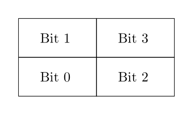
If Up, Down, Left, or Right are high on a rising clock edge, Pos should be updated accordingly (you may assume only one of these inputs will be high at a time). For example, if Pos starts as 0001 and Right is high on the next rising edge, then Pos should immediately be updated to 0100. If Right is still high on the next rising edge, then Pos should remain as 0100, as the item has reached the rightmost edge of the grid.
Permitted components: All components are permitted.
Question 8: Create a circuit that controls a timer LED, with 1-bit inputs Start/Stop, Reset, and Snooze, a 4-bit input In, and a 4-bit output Out. The timer LED should only be on when Out is exactly 0000.
While Reset is 1: On a rising clock edge, Out should be set to the value of In.
While Snooze is 1: On a rising clock edge, if the timer LED is on, then Out should be set to 0101. You may assume that Reset and Snooze will not be high at the same time.
While Start/Stop is 1: On a rising clock edge, if Reset is low, then the value of Out should decrement by 1. When Out reaches 0000, it should stay at that value.
Permitted components: All components are permitted.
Test 2 practice papers
Two practice papers are available below; the actual test will be similar in form and content.
- Practice paper A: Theory part (model answers available on submission)
- Practice paper A: Practical part (model answers)
- Practice paper B: Theory part (model answers available on submission)
- Practice paper B: Practical part (model answers)
Test 2 practice questions
We also encourage you to go back over the weekly Blackboard quizzes (for the theory part), and the weekly assignments (for the practical part). Some additional practice practical questions are below, with solutions available here. These questions are further from the exam than the practice papers above, but still practice the same skills the exam will require.
Question 1: RAM[0] contains a positive number. Your goal is to output the n’th triangular number, which is given by 1 + 2 + … + n, in RAM[1]. For example, if RAM[0] = 5, then RAM[1] should be 15.
Question 2: RAM[0] contains a positive number n. Your goal is to output the remainder on dividing n by 8, i.e. to output n % 8. For example, if RAM[0] = 12, then RAM[1] should be 4. The straightforward way of doing this in Hack runs in O(n) time. There’s also a way of doing it in O(1) time - can you find it?
Question 3: RAM[0] contains a pointer to a null-terminated string, stored character-by-character. Your goal is to compute the length of the string, not including the null terminator, and output the result to RAM[1]. (The encoding for ‘\0’ in Hack is 0.) This is the same behaviour as the strlen function in C. For example, if the input is:
RAM[0] = 20
RAM[20] = 'T'
RAM[21] = 'e'
RAM[22] = 's'
RAM[23] = 't'
RAM[24] = 0
then the output should have RAM[1] = 4.
Question 4: RAM[0] and RAM[1] contain pointers to null-terminated strings, stored character-by-character. Your goal is to concatenate the two strings and store the (null-terminated) result in the first string. This is the same behaviour as the strcat function in C. For example, if the input is:
RAM[0] = 100
RAM[1] = 200
RAM[2] = 300
RAM[100] = 'H'
RAM[101] = 'e'
RAM[102] = 'l'
RAM[103] = 'l'
RAM[104] = 'o'
RAM[105] = 0
RAM[200] = ' '
RAM[201] = 'w'
RAM[202] = 'o'
RAM[203] = 'r'
RAM[204] = 'l'
RAM[205] = 'd'
RAM[206] = '!'
RAM[207] = 0
then the desired output is:
RAM[100] = 'H'
RAM[101] = 'e'
RAM[102] = 'l'
RAM[103] = 'l'
RAM[104] = 'o'
RAM[105] = ' '
RAM[106] = 'w'
RAM[107] = 'o'
RAM[108] = 'r'
RAM[109] = 'l'
RAM[110] = 'd'
RAM[111] = '!'
RAM[112] = 0

RAM[200] = ' '
RAM[201] = 'w'
RAM[202] = 'o'
RAM[203] = 'r'
RAM[204] = 'l'
RAM[205] = 'd'
RAM[206] = '!'
RAM[207] = 0
You may assume that there is enough room to store the concatenated string starting from RAM[RAM[0]] without running into the string stored at RAM[RAM[1]].
Question 5: RAM[0] contains a positive number n, and RAM[1] contains a positive number “base” which is a pointer to the base of an n-element integer array stored in RAM[base], RAM[base+1], …, RAM[base+n-1]. Your goal is to sort this array in place in increasing order. For example, if the input is:
RAM[0] = 5
RAM[1] = 20
RAM[20] = 45
RAM[21] = 24
RAM[22] = 85
RAM[23] = -2
RAM[24] = 0
then the desired output is:
RAM[20] = -2
RAM[21] = 0
RAM[22] = 24
RAM[23] = 45
RAM[24] = 85
The easiest way to do this in Hack assembly is using bubble sort from Programming in C.
Question 6: A prime number is a positive whole number divisible by only itself and 1, not including 1. For example, the prime numbers less than 20 are 2, 3, 5, 7, 11, 13, 17 and 19. RAM[0] contains a positive whole number n. Your goal is to output a sorted list of all the prime numbers from 1 to n into memory, starting from RAM[50] and ending the output with a -1. For example, if RAM[0] = 19, then the desired output is:
RAM[50] = 2
RAM[51] = 3
RAM[52] = 5
RAM[53] = 7
RAM[54] = 11
RAM[55] = 13
RAM[56] = 17
RAM[57] = 19
RAM[58] = -1
The easiest way to do this quickly, without needing any multiplication operations, is the “sieve of Eratosthenes”. This algorithms works as follows, using the fact that any non-prime number is divisible by some prime number. Set aside an area of memory starting at RAM[101] (say). It will always be true that if RAM[100+i] = 1 for some i between 1 and n, then the algorithm currently thinks i is a prime, and otherwise, the algorithm currently thinks i isn’t prime. The algorithm starts out assuming everything is prime and will mark non-prime numbers off as it goes, so initially, RAM[101] should be 0 (since 1 is non-prime and also an annoying special case) and RAM[102], …, RAM[100+n] should be 1.
Suppose for the sake of concreteness that n = 100; then this is how the sieve will operate. We first look at RAM[102]. Since 2 is still marked as prime (i.e. RAM[102] = 1), we want to mark all the numbers from 3 to n which are divisible by 2 as non-prime. So we set RAM[104] = RAM[106] = … = RAM[200] = 0, leaving RAM[102] = 1.
Next we look at RAM[103]. Since 3 is still marked as prime (i.e. RAM[103] = 1), we want to mark all the numbers from 4 to n which are divisible by 3 as non-prime. So we set RAM[106] = RAM[109] = … = RAM[199] = 0, leaving RAM[103] = 1 and not writing to RAM[202]. It doesn’t matter that we already set RAM[106] to zero earlier - it doesn’t hurt anything to do it twice, and it’s faster not to check.
Next we look at RAM[104]. Since 4 is now marked as non-prime (from when we looked at RAM[102]), and we only need to look for prime factors in checking whether 5, 6, …, 100 are non-prime, we don’t need to check whether they’re divisible by 4 and we move straight on to RAM[105]. Since 5 is still marked as prime, we set RAM[110] = RAM[115] = … = RAM[200] = 0, and we then move on to RAM[106]. And so on and so on, all the way up to RAM[200]. (Strictly speaking we can stop at RAM[100 + sqrt(n)], but this is more of a pain to implement.) There’s nothing special about n = 100 here - other values of n work the same way, iterating over memory values from RAM[101] to RAM[100+n].
At this point, RAM[100+i] = 1 if 1 is prime and 0 if i is composite. (At the start of checking for divisibility by i, the status of RAM[100], …, RAM[100+i] are all locked-in and accurate.)
From here you should be able to generate the required sorted list of primes.
If you’ve implemented the algorithm efficiently, then it will run in time O(n + n/2 + n/3 + 1 + n/5 + 1 + n/7 + 1 + 1 + 1 + n/11 + … + 1 + 1), where each prime number p below n contributes n/p and each composite number contributes 1. By a result called Merten’s theorem, it turns out that this is the same as O(n*log log n), so it’s pretty quick!